SCOREDUINO-DMD module allows you to build 30+ types of digital scoreboards for cricket and soccer/football. All the scoreboards operate with SCOREDUINO app.

To build a single display digital scoreboard, you need to collect these components:
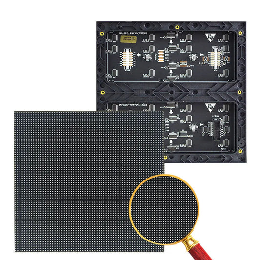
- 2 x P10 dot matrix displays
- 2 x 16 pin IDC cable (included with the dot matrix display)- one long 50cm cable, one short 10-20cm.
- 2 x Power cables (included with each dot matrix display)
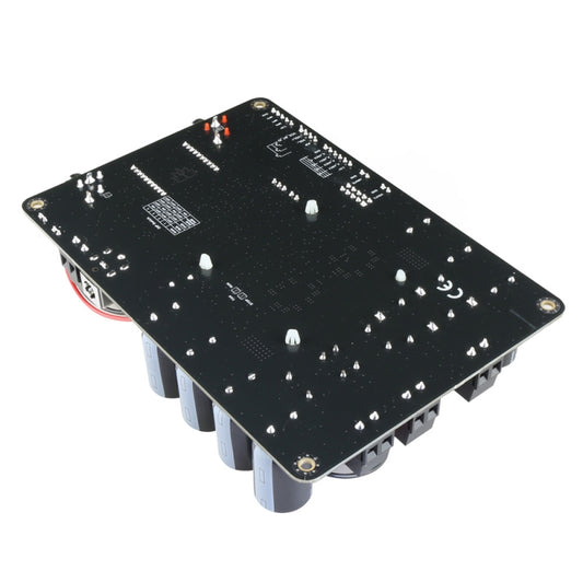
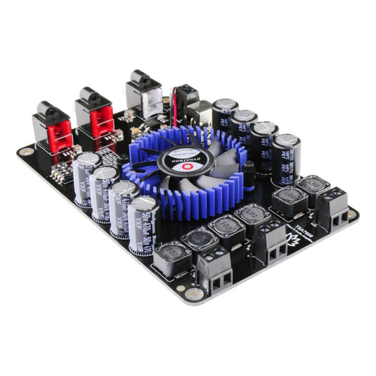
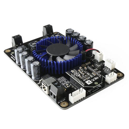
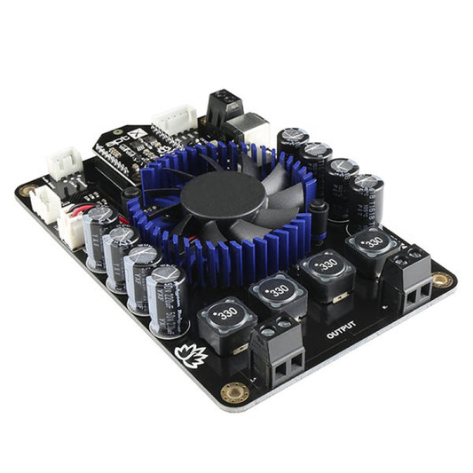
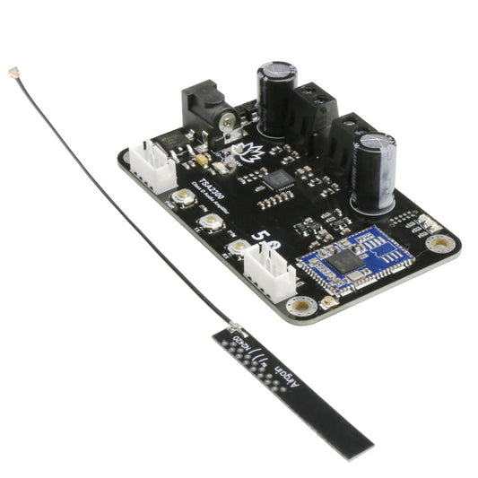
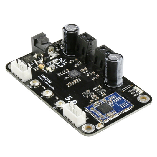
- 1 x SCOREDUINO-DMD module. 1 module-1 output, meaning each module provides only one output. Choose the output while placing the order
- 1 x HC-06 Bluetooth Module
- 1 x 5V 5A power supply
Any type of scoreboard can be built with the following 4 steps:
Step 1: PREPARATION: Utilize the assembly documents provided, customized for different scoreboard types, to prepare the Scoreboard unit.
Step 2: CONNECTION: Link the Scoreboard unit to the Scoreduino DMD module.
Step 3: POWER UP: Activate both the module and the Scoreboard unit from the preceding step.
Step 4: OPERATION: Seamlessly operate the Scoreboard with the Scoreduino App.
Read this tutorial- How to build a usable enclosure for your digital scoreboard ?
The clear images will give you excellent hint to build your first SCOREDUINO-DMD based scoreboard.
Let's start.
Step 1: PREPARE THE SCOREBOARD UNIT
Each dot matrix display includes the following set of parts:

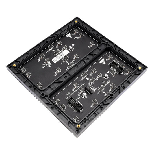
You will see arrows at the back of the display, 1 or 2 arrows pointing upward and 1 or 2 arrows to your right. Keep the displays on your table exactly as shown on the image below.


Some boards also have arrows as shown below

Connect 16 pins IDC cables and power cables as shown on the images below


RED wire goes to VCC pin- BLACK wire goes to GND pin
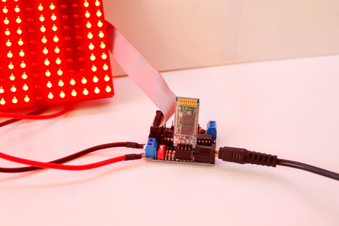
Step 2: CONNECT THE SCOREBOARD UNIT TO THE SCOREDUINO-DMD
- Connect the power cable to the screw terminal of SCOREDUINO-DMD module using a screw driver.
- Plug the IDC cable into the IDC socket on the SCOREDUINO-DMD board.
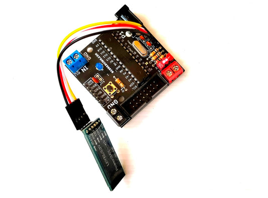
- Attach the HC-06 Bluetooth module to the SCOREDUINO-DMD board.


Step 3: POWER UP 5V 5Amp
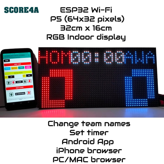
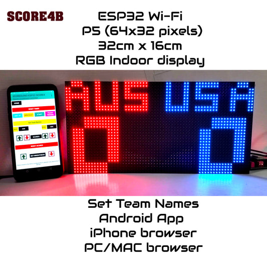
Upon activating the module, the display will promptly showcase the output corresponding to your selected purchase. 1 board gives only 1 output.

Step 4: Operate using Scoreduino App
Open the SCOREDUINO App and operate the scoreboard, up down counter or timer.

How to use the Scoreduino App ?
- Pair your phone with the Bluetooth module using code: 1234.
- Connect to the Bluetooth module(Name: SCOREDUINO) via the App
- Operate the Scoreboard/Timer/Counter
Read this tutorial- How to build a usable enclosure for your digital scoreboard ?
Click on the images below to see the outputs
SCOREDUINO-DMD is pre-programmed with 6 outputs- 1 board has only 1 output.
Check out this page for all the possible outputs.
Flickr Images- All outputs in 5 colors- RED, BLUE, GREEN, WHITE and YELLOW


Leave a comment