- Home
- Triple Axis Accelerometer ADXL345
Product Categories
- FREE SHIPPING Items (5)
- Bluetooth Audio Amplifier (27)
- Bluetooth Audio Amplifier (Apt-X) (29)
- Bluetooth Audio Receiver/Transmitter modules (26)
- Bluetooth Audio volume controller (3)
- Bluetooth Relays (16)
- Digital Menu and Calenders (3)
- Scoreduino (11)
- RGB Scoreboards- Wi-Fi (10)
- Digital Scoreboards- Bluetooth (32)
- Scoreduino DMD- Bluetooth (15)
- Dot Matrix Displays (11)
- Arduino Modules (13)
- Arduino Shields (6)
- Counters (7)
- DIY Kits (17)
- Lazybones (2)
- Bluetooth Relays (16)
- RF Relays (7)
- Timer Relays (9)
- USB Relays (19)
- FM transmitters (3)
- Buck and Boost Modules (1)
- Power supplies (9)
Featured product
Description
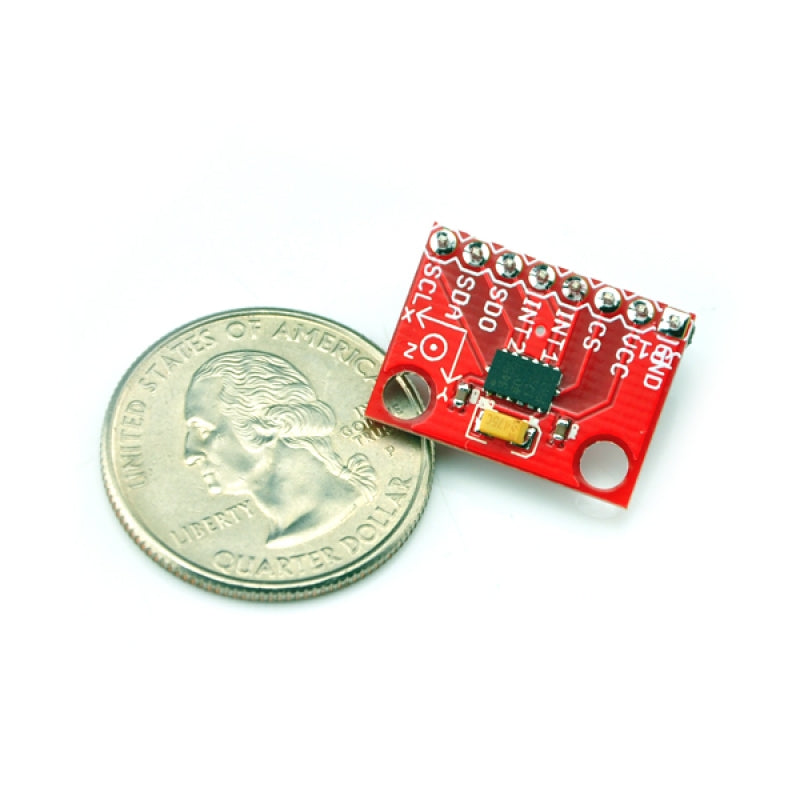
The ADXL345 is a small, thin, low power, 3-axis accelerometer with high resolution (13-bit) measurement at up to ±16 g. Digital output data is formatted as 16-bit twos complement and is accessible through either an SPI (3- or 4-wire) or I2C digital interface.
The ADXL345 is well suited to measures the static acceleration of gravity in tilt-sensing applications, as well as dynamic acceleration resulting from motion or shock. Its high resolution (4 mg/LSB) enables measurement of inclination changes less than 1.0°.
Several special sensing functions are provided. Activity and inactivity sensing detect the presence or lack of motion and if the acceleration on any axis exceeds a user-set level. Tap sensing detects single and double taps. Free-fall sensing detects if the device is falling. These functions can be mapped to one of two interrupt output pins. An integrated, patent-pending 32-level first in, first out (FIFO) buffer can be used to store data to minimize host processor intervention. Low power modes enable intelligent motion-based power management with threshold sensing and active acceleration measurement at extremely low power dissipation.
Specification
- 2.0-3.6VDC Supply Voltage
- Ultra Low Power: 40uA in measurement mode, 0.1uA in standby@ 2.5V
- Tap/Double Tap Detection
- Free-Fall Detection
- SPI and I2C interfaces
Hooking it Up:
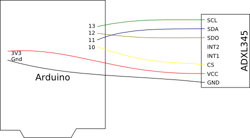
Here is the guide illustrates how to connect an Arduino to the ADXL345 breakout board. The following is a table describing which pins on the Arduino should be connected to the pins on the accelerometer:
| Arduino Pin | ADXL345 Pin |
| 10 | CS |
| 11 | SDA |
| 12 | SDO |
| 13 | SCL |
| 3V3 | VCC |
| Gnd |
GND |
Test Code:
//Add the SPI library so we can communicate with the ADXL345 sensor
#include <SPI.h>
//Assign the Chip Select signal to pin 10.
int CS=10;
//This is a list of some of the registers available on the ADXL345.
//To learn more about these and the rest of the registers on the ADXL345, read the datasheet!
char POWER_CTL = 0x2D; //Power Control Register
char DATA_FORMAT = 0x31;
char DATAX0 = 0x32; //X-Axis Data 0
char DATAX1 = 0x33; //X-Axis Data 1
char DATAY0 = 0x34; //Y-Axis Data 0
char DATAY1 = 0x35; //Y-Axis Data 1
char DATAZ0 = 0x36; //Z-Axis Data 0
char DATAZ1 = 0x37; //Z-Axis Data 1
//This buffer will hold values read from the ADXL345 registers.
char values[10];
//These variables will be used to hold the x,y and z axis accelerometer values.
int x,y,z;
void setup(){
//Initiate an SPI communication instance.
SPI.begin();
//Configure the SPI connection for the ADXL345.
SPI.setDataMode(SPI_MODE3);
//Create a serial connection to display the data on the terminal.
Serial.begin(9600);
//Set up the Chip Select pin to be an output from the Arduino.
pinMode(CS, OUTPUT);
//Before communication starts, the Chip Select pin needs to be set high.
digitalWrite(CS, HIGH);
//Put the ADXL345 into +/- 4G range by writing the value 0x01 to the DATA_FORMAT register.
writeRegister(DATA_FORMAT, 0x01);
//Put the ADXL345 into Measurement Mode by writing 0x08 to the POWER_CTL register.
writeRegister(POWER_CTL, 0x08); //Measurement mode
}
void loop(){
//Reading 6 bytes of data starting at register DATAX0 will retrieve the x,y and z acceleration values from the ADXL345.
//The results of the read operation will get stored to the values[] buffer.
readRegister(DATAX0, 6, values);
//The ADXL345 gives 10-bit acceleration values, but they are stored as bytes (8-bits). To get the full value, two bytes must be combined for each axis.
//The X value is stored in values[0] and values[1].
x = ((int)values[1]<<8)|(int)values[0];
//The Y value is stored in values[2] and values[3].
y = ((int)values[3]<<8)|(int)values[2];
//The Z value is stored in values[4] and values[5].
z = ((int)values[5]<<8)|(int)values[4];
//Print the results to the terminal.
Serial.print(x, DEC);
Serial.print(',');
Serial.print(y, DEC);
Serial.print(',');
Serial.println(z, DEC);
delay(10);
}
//This function will write a value to a register on the ADXL345.
//Parameters:
// char registerAddress - The register to write a value to
// char value - The value to be written to the specified register.
void writeRegister(char registerAddress, char value){
//Set Chip Select pin low to signal the beginning of an SPI packet.
digitalWrite(CS, LOW);
//Transfer the register address over SPI.
SPI.transfer(registerAddress);
//Transfer the desired register value over SPI.
SPI.transfer(value);
//Set the Chip Select pin high to signal the end of an SPI packet.
digitalWrite(CS, HIGH);
}
//This function will read a certain number of registers starting from a specified address and store their values in a buffer.
//Parameters:
// char registerAddress - The register addresse to start the read sequence from.
// int numBytes - The number of registers that should be read.
// char * values - A pointer to a buffer where the results of the operation should be stored.
void readRegister(char registerAddress, int numBytes, char * values){
//Since we're performing a read operation, the most significant bit of the register address should be set.
char address = 0x80 | registerAddress;
//If we're doing a multi-byte read, bit 6 needs to be set as well.
if(numBytes > 1)address = address | 0x40;
//Set the Chip select pin low to start an SPI packet.
digitalWrite(CS, LOW);
//Transfer the starting register address that needs to be read.
SPI.transfer(address);
//Continue to read registers until we've read the number specified, storing the results to the input buffer.
for(int i=0; i<numBytes; i++){
values[i] = SPI.transfer(0x00);
}
//Set the Chips Select pin high to end the SPI packet.
digitalWrite(CS, HIGH);
}
Shipping & Return
SHIPPING
Our default shipping method is Registered International Post with a tracking code. Alternatively, you may opt for express shipping via DHL or FedEx.
Please note that we endeavor to ship all orders within 24 to 48 hours. The typical delivery time frame ranges between 2 to 4 weeks.
Kindly be aware that unforeseen circumstances, including customs or postal delays, may occasionally affect delivery times beyond our control.
Customers are responsible for any customs charges and should verify their country's customs policy.
RETURNS
If you are dissatisfied with the product, you may initiate a return within one month from the date of delivery. Please ensure that the product is sent back to our address in Sydney, Australia. Kindly note that all shipping charges associated with the return are the responsibility of the customer.
Reviews
Related Products
Recently viewed products
Copyright © BUILDCIRCUIT.COM and SCOREDUINO.COM. All Rights Reserved.
-
WHAT ARE YOU LOOKING FOR?Search
- Login / Register
- Home
-
Shop
All categories
- FREE SHIPPING Items
- Bluetooth Audio Amplifier
- Bluetooth Audio Amplifier (Apt-X)
- Bluetooth Audio Receiver/Transmitter modules
- Bluetooth Audio volume controller
- Bluetooth Relays
- Digital Menu and Calenders
- Scoreduino
- RGB Scoreboards- Wi-Fi
- Digital Scoreboards- Bluetooth
- Scoreduino DMD- Bluetooth
- Dot Matrix Displays
- Arduino Modules
- Arduino Shields
- Counters
- DIY Kits
- Lazybones
- Bluetooth Relays
- RF Relays
- Timer Relays
- USB Relays
- FM transmitters
- Buck and Boost Modules
- Power supplies
- page
- Blog Tutorials and Documents
- Wishlist (0)
- Compare (0)
- Contact Us


