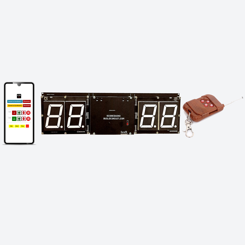
These are the pins on the Scoreduino-B board:
On the left side:
- 9V: This is to power up RED colored 2.3″ displays. We get this voltage from the voltage regulator LM78XX.
- 5V: 5V is used for CD4511 and 74LS192/CD40192 on the left side
- GND: GND of SCOREDUINO-B connects with the GND of 2 digits up/down counter
- A: Send pulse from SCOREDUINO-B via this pin in order to count UP
- B: Send pulse from SCOREDUINO-B via this pin in order to count down
- 14: Reset pin. Send pulse to reset the count.
On the right side:
- V: V depends upon the color of the displays used on the right side. For example, GREEN colored 2.3″ display needs 12V. This is the default supply voltage.
- 5V: 5V is used for CD4511 and 74LS192/CD40192 on the right side
- GND: GND of SCOREDUINO-B connects with the GND of 2 digits up/down counter
- C: Send pulse from SCOREDUINO-B via this pin in order to count UP
- D: Send pulse from SCOREDUINO-B via this pin in order to count down
- 14: Reset pin. Send pulse to reset the count.


